7 Adding an object display
In this section, you will see how to add a display to an object, how to dynamize it using relative addressing and how to add displays of object instances to the visualization.
7.1 Adding a new display to the object type
The first step is to add a new display to the object type.
Right-click on the "Light" type and select "Add display" from the menu which appears.
Type in "MainDisplay" as name for the display and add it to the object by clicking "OK".
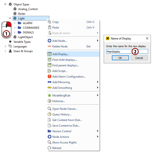
Add a display to the object
Hint
If you right-click on the new display node and open the "ModellingRule" submenu, you will notice that "Shared" is checked (default for data variables). This means that the display of the type is referenced from every object instance which you create. The display looks and behaves the same for every object instance, so it would not make sense to create a new display for every instance.
7.2 Designing an object display
7.2.1 Creating a background
Double-click on the "MainDisplay" node to open the graphics editor.
First, we draw the background of our object display. Draw a rectangle of the desired size - it is possible to change its size afterwards.
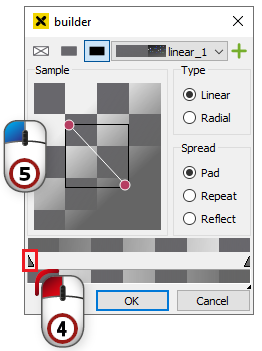
For our background we want to have a gradient fill, so make sure the rectangle is marked and click on the "fill" option just below the drawing area. In the window which appears, click on the
 symbol to choose a gradient fill.

You can change the colors of the gradient by double-clicking on the small triangles under the gradient bar.
Change the angle of the gradient by moving the red circles in the preview box. Define a matching gradient.
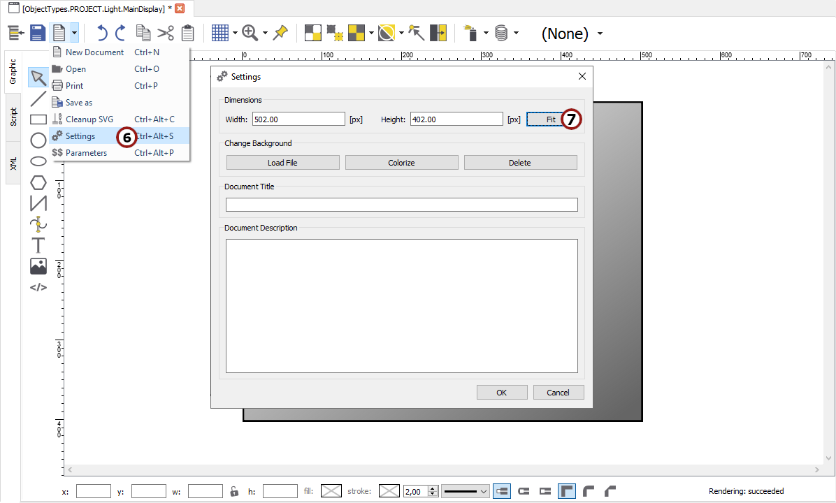
When you finish the background design, click on "File -> Settings" (
 ) in the top symbol bar.
Click on the Fit button in the dialog which appears to adjust the page size to the size of the background rectangle.
Create a background for "MainDisplay"
7.2.2 Drawing a bulb
We want to display our "LightIntensity" input variable through the color of a light bulb.
Draw a small rectangle in the middle of the left side of the object display.
Draw a circle on top of the rectangle to make it look like a bulb.
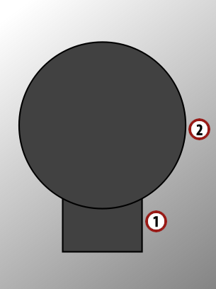
Try to draw a form that looks like a bulb
7.2.3 Adding and parameterizing three buttons
We also want to set the value of the "LightIntensity" output, so we want to add three buttons for 0 %, 50 % and 100 % light intensity to our display.
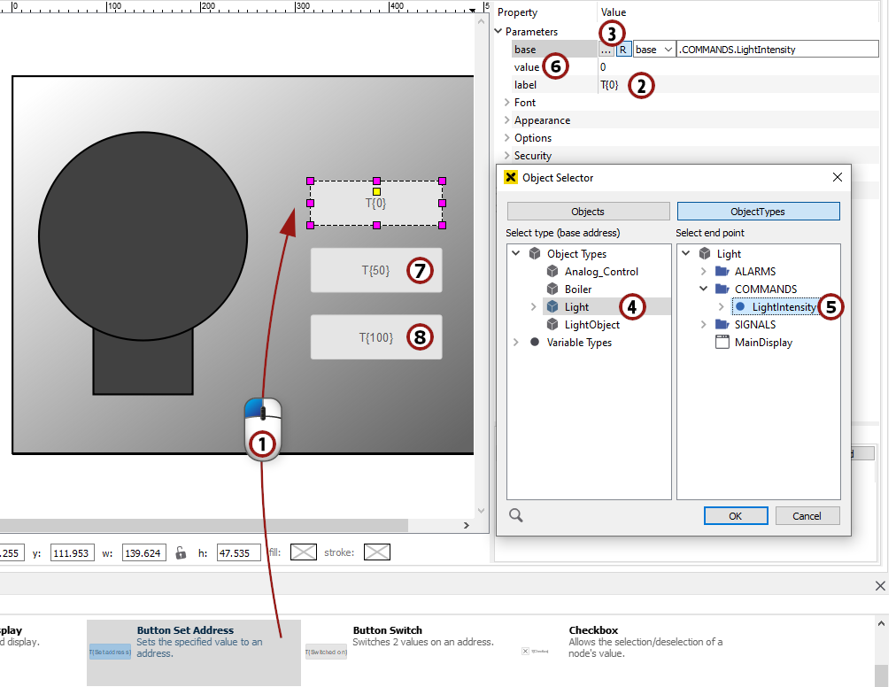
In the bottom area of the graphics editor you can see a selection of predefined controls. Drag & drop the "Button Set Address" control into your drawing area.
On the right side, you can see a list of all parameters of the referenced control. Set the text of the button by entering "0" in the "label" field.
To set its "base" parameter, click the
 button to activate relative addressing, then the
  button to open the node select dialog.
Hint
Relative addressing can be used only in conjunction with modellingrule "New". If a variable type or object type contains a node defined with modellingrule "Shared", this node can be addressed only absolutely. This is a consequence of the fact, that one node can only have one node id.
E.g: if LightIntensity would be defined with modellingrule "Shared", then change following steps:
Relative addressing must be deactivated by releasing the
button.In the left box, you must select the ObjectTypes
In the right box you must select "ObjectTypes -> Light -> COMMANDS -> LightIntensity"..
In the left box, you can select the object type for the relative addressing, so click on "Light".
In the right box you can select the variable whose change you want to react to, so select "COMMANDS -> LightIntensity". Apply the dialog by clicking "OK".
Set the "value" parameter by entering "0". This value will be set to the base when the button is clicked.
Add a button with the label "50" and value "50" the same way.
Add a button with the label "100" and value "100" the same way.
We are done with the design of our object display for now, so click on the
 symbol to save it.
Adding and parameterizing three buttons to set "LightIntensity"
7.3 Color change of the light bulb to display the light intensity
In this section, we want to add a simple dynamic to our bulb to display the light intensity.
Click on the circle of the bulb to mark it and open the "Simple Dynamics" dialog as described in section 4.4.1
Hint
If you have worked through section 4, you are already familiar with this dialog. The only new thing is that we want to address our data variables relatively.
Choose
 from the possibilities on the left.
Click on the
button to activate relative addressing and open the "Object Selector" by clicking on .In the left box, you can select the object type for the relative addressing, so click on "Light".
In the right box you can select the variable whose change you want to react to, so select "SIGNALS -> LightIntensity". Apply the dialog by clicking "OK".
We want to change the color of the circle, so we choose
 on the left in the ACTION section.
The range of our "LightIntensity" variable is from 0 - 100, so we choose "Value Range" as the type and enter the minimum and maximum values.
We want to display the circle in a color range from gray to yellow, so we check the fill box and choose a gray color as the start fill and a yellow color as the stop fill by clicking on
.Hint
If the value of the data variable is 0, the start fill will be displayed, if it is 100, the stop fill will be displayed. Values in between are merged according to the gradient from the start fill to the stop fill.
We are now finished with the dynamization. Apply the dialog by clicking "OK".
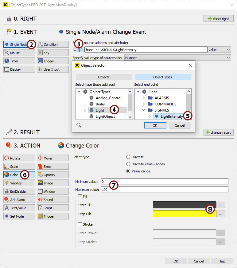
"Simple Dynamics" dialog for the circle of our light bulb
For now we are done with the dynamization. We will take a look at how to handle alarms in section 9.
7.4 Adding objects to the visualization
In this section we will add the five light objects to a display so they can be seen in the visualization.
For this purpose, add a new display to the MAIN menu called "OfficeLight" as described in section 3.1.
Double-click on the display to open the graphics editor for it.
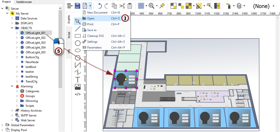
Click on "File -> Open file" (
 ) and in "[atvise directory]/library/displays", choose the file named "office_light_bg.svg". This file shows a floor plan of the office in which we want to display our five lights.
Now we want to add the five light objects to this display. For this purpose open the "Server -> My Servers -> Objects" folder on the left in the atvise builder interface.
Click on the top node of the first object instance ("OfficeLight_001") and drag & drop it in the drawing area of the graphics editor.
Do this with all five object instances, positioning them in the five offices with a blue background and save the display.
Open the "OfficeLight" display in the browser of your choice as described in section 3.1.
Change the "LightIntensity" of one of the objects using the buttons.
Hint
The value of COMMANDS.LightIntensity is changed, written to the "TestServer" and the SIGNALS.LightIntensity data variable is given the new value which is displayed through the color of the circle.
Adding the objects to a display