8 Parameterization option 3 - display at the object type
In this section you will learn how to add a display to an object type, how to dynamize it using relative addressing and how to add displays of object instances to the visualization.
Hint
Use this type of parameterization to create object displays for object types you have defined in the import XML file.
8.1 Adding a new display to the object type
The first step is to add a new display to the object type.
Open the Servers ‣ DemoServer ‣ OBJECTS folder and right-click on the "L001" object.
Choose from the menu which appears.
Type in "MainDisplay" as name for the display and add it to the object by clicking OK.
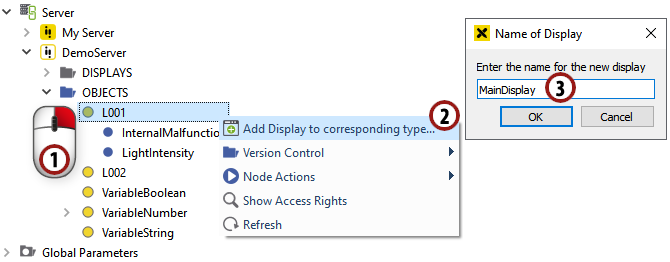
Add a display to the object
8.2 Designing an object display
Design the "MainDisplay" similar to section 6.3. You can also copy the elements from the display you have drawn in section 6.3 and remove the dynamics afterwards as described in section 7.2.
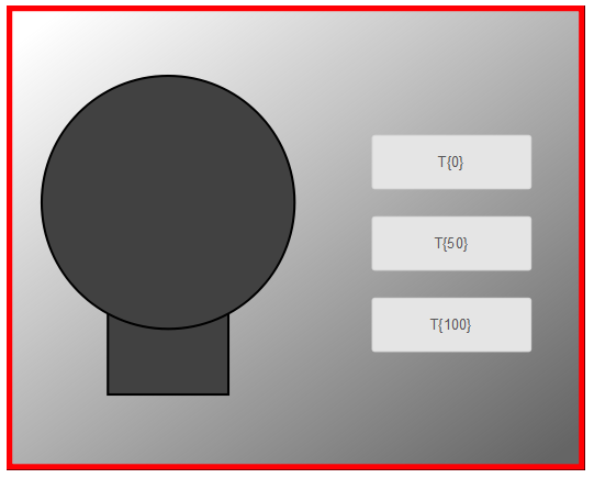
Designing an object display
8.3 Adding dynamization
In this section we want to use predefined controls and simple dynamics to add dynamization to our object display.
8.3.1 Parameterizing the three buttons
We want to set the value of LightIntensity, so we have to parameterize the three buttons for 0 %, 50 % and 100 % light intensity.
Click on one of the three buttons to mark it.
On the right side, you can see a list of all parameters of the button. Set the text of the button by entering "0" in the "label" field.
To set its "base" parameter, click the
 button to activate relative addressing, then the
  button to open the node select dialog.
In the left box you can select the object type for the relative addressing, so click on Variable Types ‣ OfficeLight.
In the right box you can select the variable whose change you want to react to, so select "LightIntensity". Apply the dialog by clicking OK.
Set the "value" parameter by entering "0". This value will be set to the base address when clicking the button.
Parameterize a button with the label "50" and value "50" the same way.
Parameterize a button with the label "100" and value "100" the same way.

Parameterizing the three buttons using relative addressing
8.3.2 Color change of the light bulb to display the light intensity
In this section, we want to add a simple dynamic to our bulb to display the light intensity.
1 Click on the circle of the bulb to mark it and open the "Simple Dynamics" dialog as described in section 5.3.1.
Hint
The simple dynamics in this section will be similar to section 7.4., but this time the object display is located directly in the object type, so we can use the default base parameter for the object's base address.
Choose
 from the possibilities on the left.
Click on the
button to activate relative addressing and open the "node select dialog" by clicking on .In the left box you can select the object type for the relative addressing, so click on Variable Types ‣ OfficeLight.
In the right box you can select the variable whose change you want to react to, so select "LightIntensity". Apply the dialog by clicking OK.
We want to change the color of the circle, so we choose
 on the left in the ACTION section.
The range of our "LightIntensity" variable goes from 0 - 100, so we choose "Value Range" as the type and enter the minimum and maximum values.
We want to display the circle in a color range from gray to yellow, so we check the fill box and choose a gray color as the start fill and a yellow color as the stop fill by clicking on
.We are now finished with the dynamization. Apply the dialog by clicking OK.
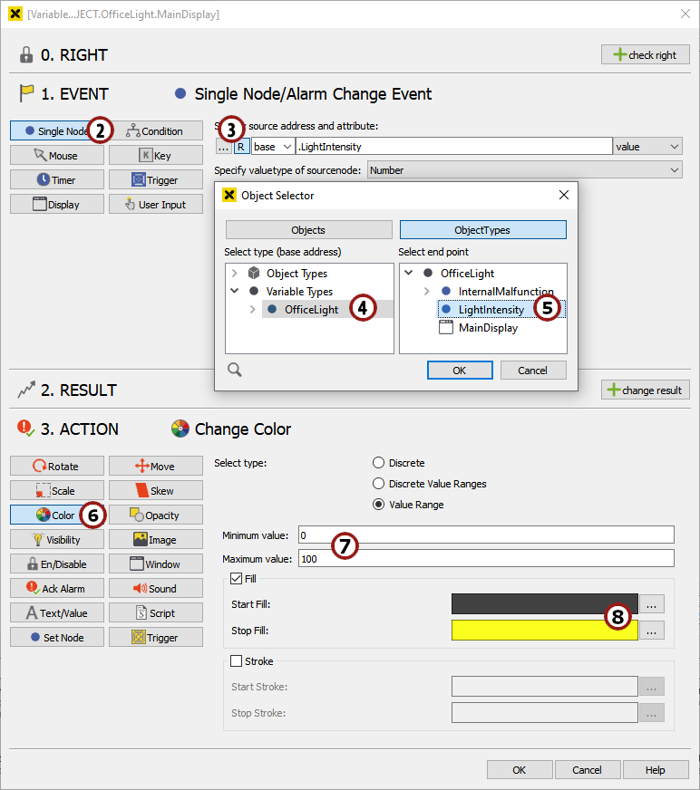
"Simple Dynamics" dialog for the circle of our light bulb
8.3.3 The visibility of the malfunction border
Mark the red border and open the "Simple Dynamics" dialog as described in section 5.3.1.
Choose
from the possibilities on the left.We want to add a relative address, so click the
button and open the "node select dialog" by clicking on .In the left box you can select the object type for the relative addressing, so click on Variable Types ‣ OfficeLight.
In the right box you can select the variable whose change you want to react to, so select "InternalMalfunction". Apply the dialog by clicking OK.
We want to change the visibility of the border, so choose
 in the ACTION part.
If the value is true, we want the border to be visible, so choose "visible" for this condition. Add a second condition by clicking on
 , changing the value column to "false" and choosing "invisible".
Apply the "Simple Dynamics" dialog by clicking OK.
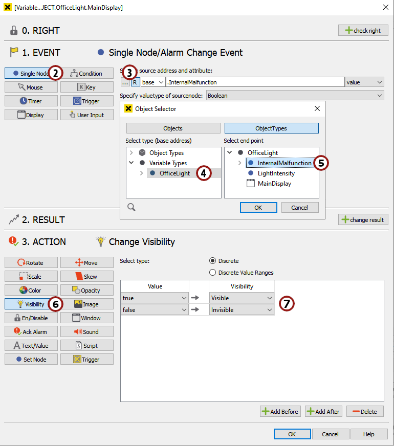
Changing the visibility of the border in dependence on a boolean value
Now we have finished the engineering of our object display.
8.4 Adding objects to Light_Background
Open the "Light_Background" display (which we added in step 6.1).
Drag & drop the objects L001 and L002 from the DemoServer into the "Light_Background" display.
Drag & drop the Objects ‣ L001 ‣ InternalMalfunction variable into the "Light_Background" display. A small button will appear which can be used to set the variable in the visualization.
Repeat 3, but now drag & drop Objects ‣ L002 ‣ InternalMalfunction into the display .
Position the two object displays in rooms of your choice.
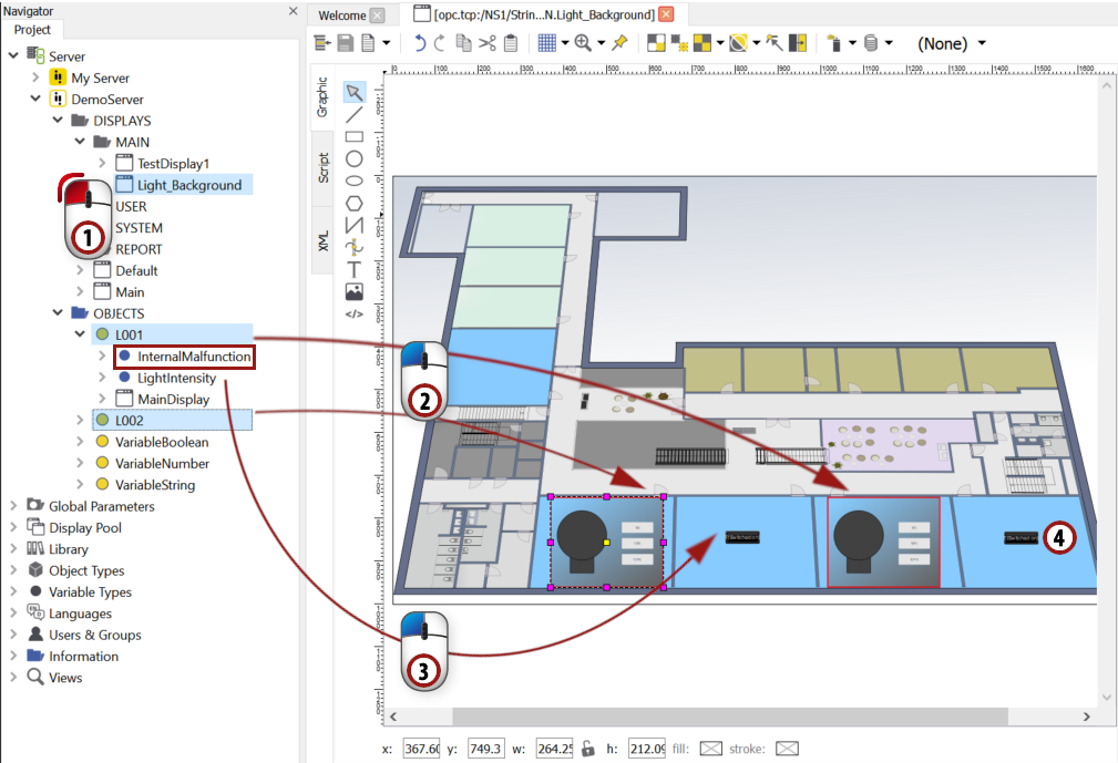
Dragging & dropping the OfficeLight objects into the display
8.5 Generating and viewing the visualization
Save the display by clicking  and generate the visualization by choosing . Then start a web browser (as described in section 4) and view the "Light_Background" display in the visualization. Set the value of the light intensity of one of the objects using the three buttons and see how the color of the bulb changes. Also use the InternalMalfunction buttons to make the red border appear and disappear.